Application of cutting blade and casing in full casing construction
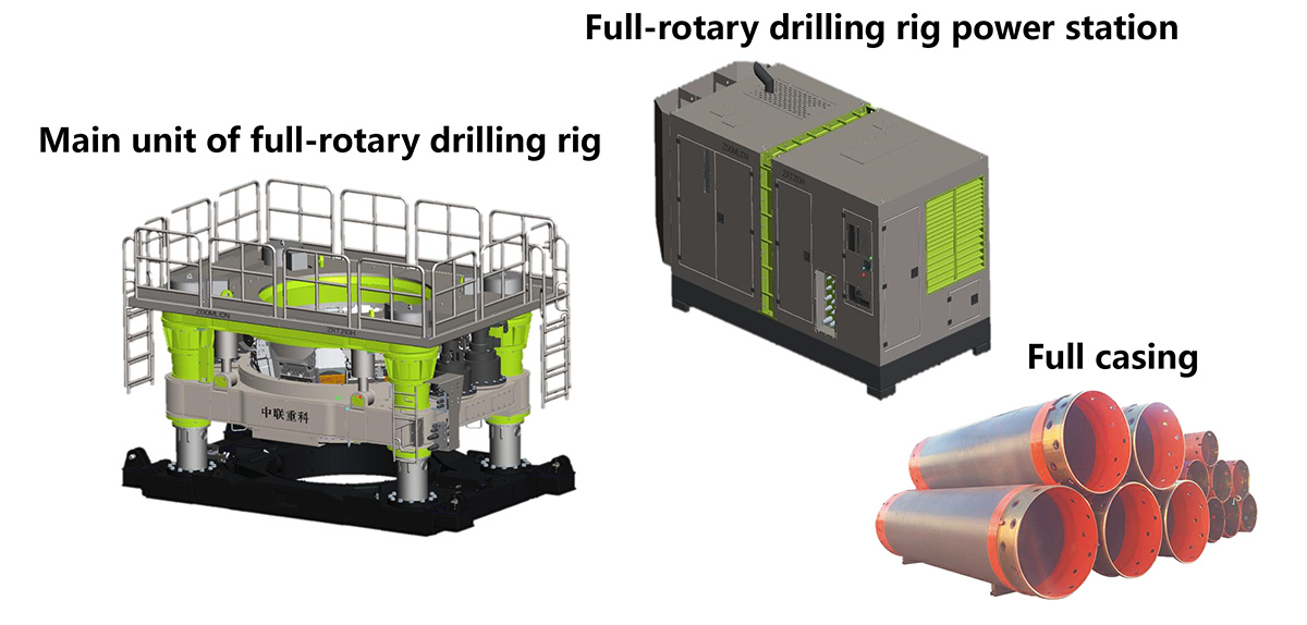
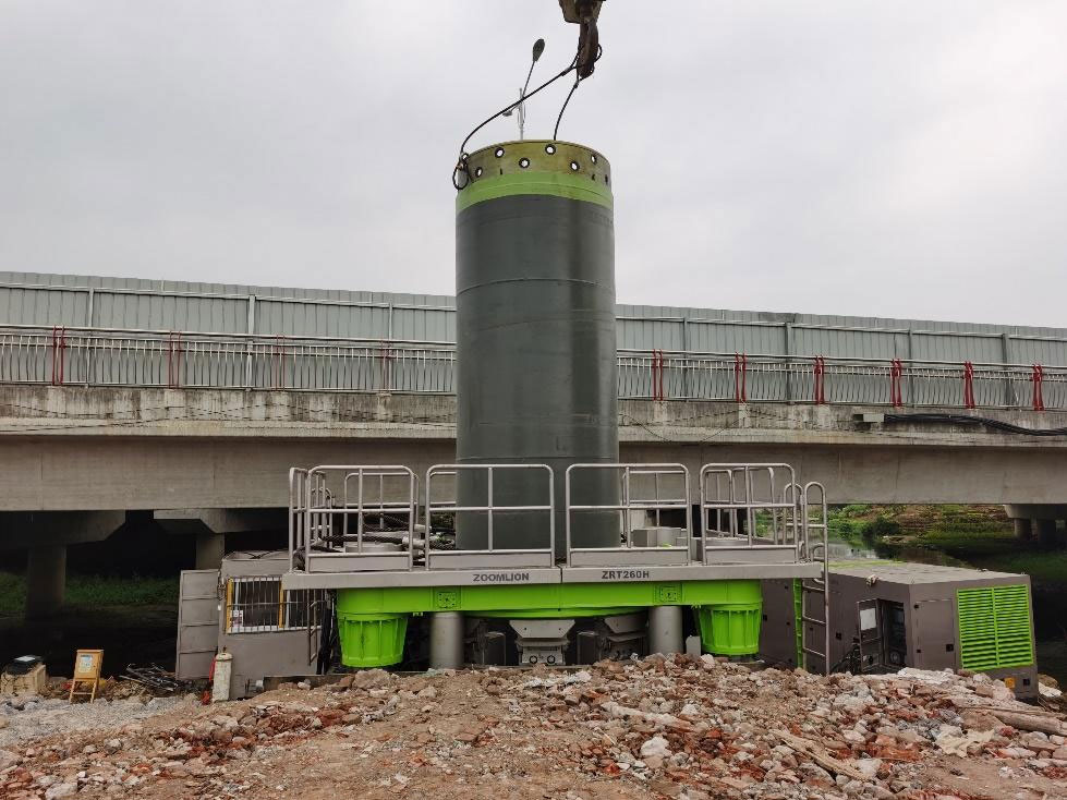
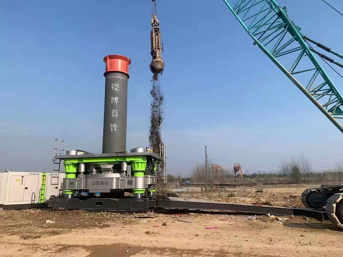
The complete rotary drilling rig, including the power station and the working device, derives its power from the power station.
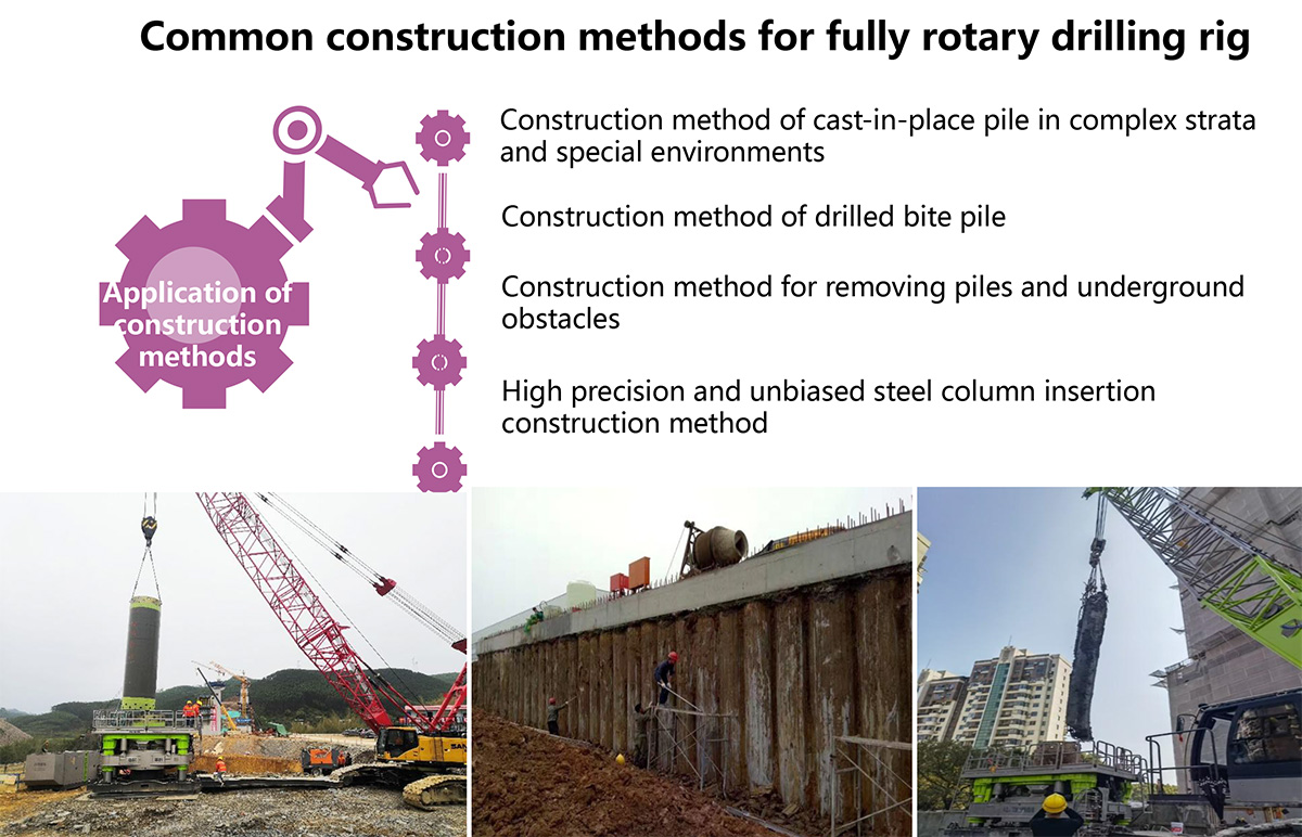
Common construction methods for full-rotary drilling rigs
Use of complete casing and cutting tools
During the construction process of the full casing and full rotary drilling rig, it is necessary to cut sandy clay, quicksand, bedrock, block stones, isolated stones, etc. The installation of the cutting tool and maintenance of the casing have a significant impact on the efficiency of rotary cutting, and also determine the life of the cutting tool, which is often overlooked in the actual construction process. This article introduces the installation methods of cutting tools and the maintenance and use of casing according to different geological conditions and construction requirements.
Selection and configuration of cutting heads for full casing construction
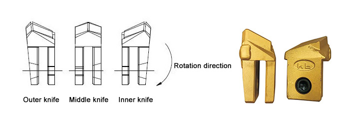
1. The shape of the cutting blade:
The cutting blades used in the construction of full casing and full rotary drilling rigs can be divided into outer blades (teeth), middle blades (teeth), and inner blades (teeth) according to their shapes.
Selection and configuration of cutting heads for full casing construction
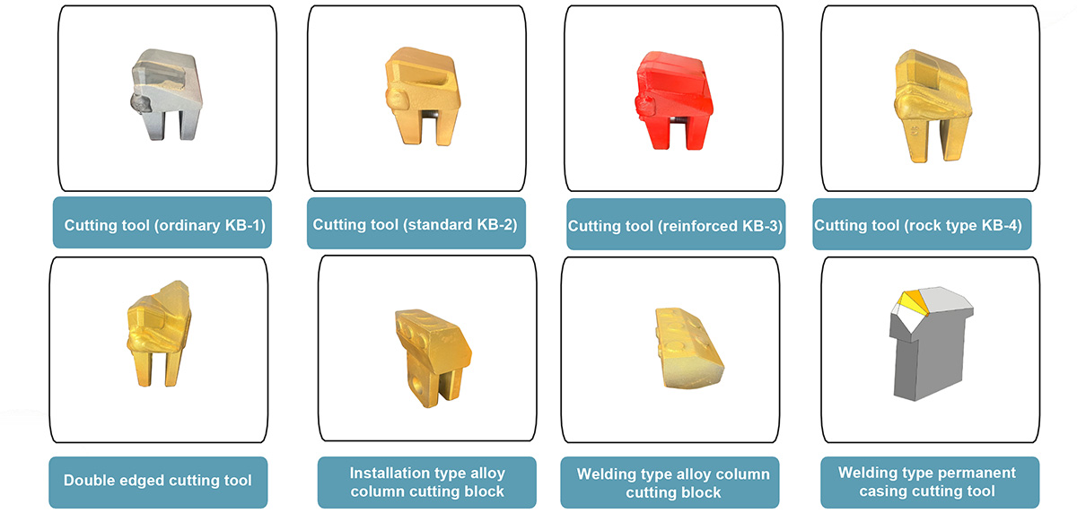
2. Types of cutting tools:
|
Model |
KB-1 |
KB-2 |
KB-3 |
KB-4 |
|
Applicable rock |
Soft rock type |
Soft to medium hard rock type |
Medium hard rock type |
Hard rock type |
Selection and configuration of cutting tools for full casing construction
3. Installation of cutting tool
(1) The number and arrangement of cutting blades should be adjusted appropriately according to the geological conditions of the construction site, and the distance between each cutting blade should be controlled within the range of 170-220mm. Generally, the number of cutting blades can be selected according to Table 1.
Table 1: Number of cutting tools for casing with different diameters
|
Nominal diameter of casing (mm) |
Φ1000
-Φ1100 |
Φ1200
-Φ1400 |
Φ1500
-Φ1700 |
Φ1800 |
Φ2000 |
Φ2200 |
Φ2400
Φ2500 |
Φ2600
Φ2800 |
Φ3000 |
Φ3200 |
|
Number of blade heads (pieces) |
18 |
21 |
24 |
27 |
30 |
33 |
36 |
39 |
42 |
45 |
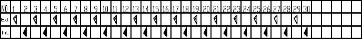
(2) Different numbers and arrangements of external teeth, middle teeth, and internal teeth have different cutting effects and efficiencies. Adjusting the number and arrangement of external teeth, middle teeth, and internal teeth according to the geological conditions of the construction site can improve drilling efficiency. The arrangement of blade heads mainly has the following modes.
Selection and configuration of cutting blades for full casing construction
Installation mode A: Using 50 soft rock type cutting tool
For ordinary strata, underground obstacles, small diameter boulders, block stone strata, etc., the standard arrangement of external teeth, internal teeth, external teeth, and internal teeth circulation can meet the construction requirements.
Installation mode: number of cutting tool heads arranged
|
Nominal diameter of casing (mm) |
Number of cutting heads (pieces) |
|
Outer teeth |
Densmedius |
Internal tooth |
Amount to |
|
Φ1000 |
12 |
0 |
6 |
18 |
|
Φ1200 |
14 |
0 |
7 |
21 |
|
Φ1500 |
16 |
0 |
8 |
24 |
|
Φ2000 |
20 |
0 |
10 |
30 |
|
Φ2500 |
24 |
0 |
12 |
36 |
|
Φ3000 |
28 |
0 |
14 |
42 |
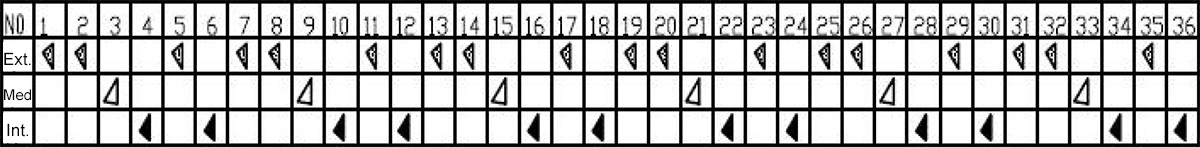
Selection and configuration of cutting tools for full casing construction
Installation mode B: Using 50 software Medium hard cutting tool and 50 hard cutting tool
For moderately weathered rock layers and larger rock blocks and boulders with diameters close to the casing, the installation method of the cutting head should generally adopt external teeth, external teeth, middle teeth, internal teeth, external teeth, and internal teeth.
Installation mode: Number of cutting tool arrangements
Nominal diameter of casing
(mm) |
Number of cutting tools (pieces) |
|
Outer teeth |
Densmedius |
Internal tooth |
Amount to |
|
Φ1000 |
10 |
3 |
5 |
18 |
|
Φ1200 |
12 |
3 |
6 |
21 |
|
Φ1500 |
12 |
4 |
8 |
24 |
|
Φ2000 |
16 |
5 |
9 |
30 |
|
Φ2500 |
19 |
7 |
10 |
36 |
|
Φ3000 |
22 |
8 |
12 |
42 |
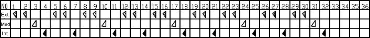
Installation mode C: using 50 hard type cutting tools and 50 hard rock type cutting tools
For rock formations with high strength and difficult to cut (such as requiring the use of impact hammers and rolling cutters for construction), the installation method of cutting tools can generally adopt a cyclic arrangement of external teeth, external teeth, middle teeth, internal teeth, external teeth, external teeth, and internal teeth.
Installation mode: Number of cutting tool arrangements
Nominal diameter of casing
(mm) |
Number of cutting tools (pieces) |
|
External teeth |
Middle teeth |
Internal teeth |
Amount to |
|
Φ1000 |
10 |
3 |
5 |
18 |
|
Φ1200 |
12 |
3 |
6 |
21 |
|
Φ1500 |
12 |
4 |
8 |
24 |
|
Φ2000 |
16 |
5 |
9 |
30 |
|
Φ2500 |
19 |
7 |
10 |
36 |
|
Φ3000 |
22 |
8 |
12 |
42 |
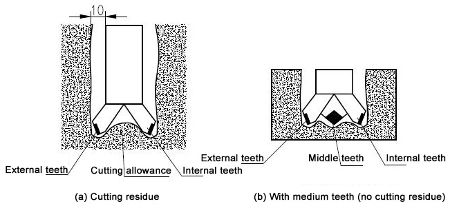
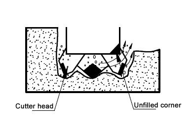
When cutting soft and medium hard rock layers, the rock will peel off or be damaged or crushed in the textured areas (cracks or gaps between rock layers) due to cutting resistance, so there will be little accumulation in the cutting groove. However, large and hard rock blocks or hard rock layers that exceed the diameter of the casing have few textures and are difficult to be destroyed, resulting in cutting grooves along the trajectory of the cutting tool. In this state, cutting residues will be generated between the inner and outer edges, increasing drilling resistance. Installing middle teeth can eliminate cutting residues and improve drilling and cutting efficiency.
In the process of cutting bedrock, it is necessary to scientifically arrange the cutting blades to smoothly discharge the debris, and ensure that the cutting edge of the cutting blade protrudes about 10mm inward and outward from the side of the casing to ensure sufficient clearance between the casing side and the hole wall, reducing surface friction. But if the protrusion is too large, it will cause excessive load on the cutting tool, affecting the service life of the cutting tool.
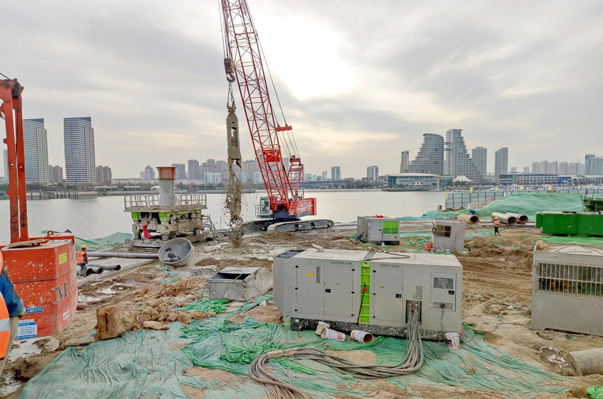
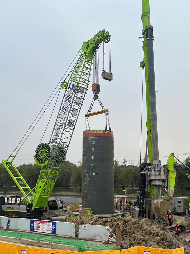
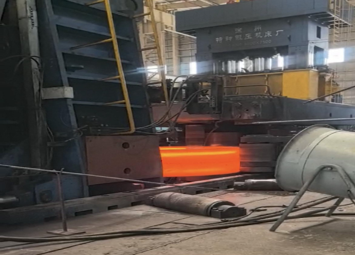
Schematic diagram of construction status of fully rotary drilling rig
Installation of bottom pipe and knife holder
1. Full casing material
1) Selection of casing body material: For general sandy soil, short pile length, and light load conditions, Q345B carbon steel material can be used for the casing body. For working conditions that require cutting block stones, isolated stones, obstacles, bedrock, or long piles, the casing cutting bucket should be made of materials with better performance, and should be made of 25CrMo alloy steel forgings and welded.
2) Selection of bottom casing wall thickness: Due to the different frictional resistance and rotational torque experienced by casing of different diameters during construction, for piles of the same length, the larger the diameter, the greater the frictional resistance and rotational torque experienced by the casing. Therefore, different diameters of bottom casing have different requirements for wall thickness.
|
Diameter of casing (mm) |
Φ1000—Φ1500 |
Φ2000 |
Φ2500—Φ3000 |
|
Wall thickness of casing (mm) |
30 |
30-35 |
40-50 |
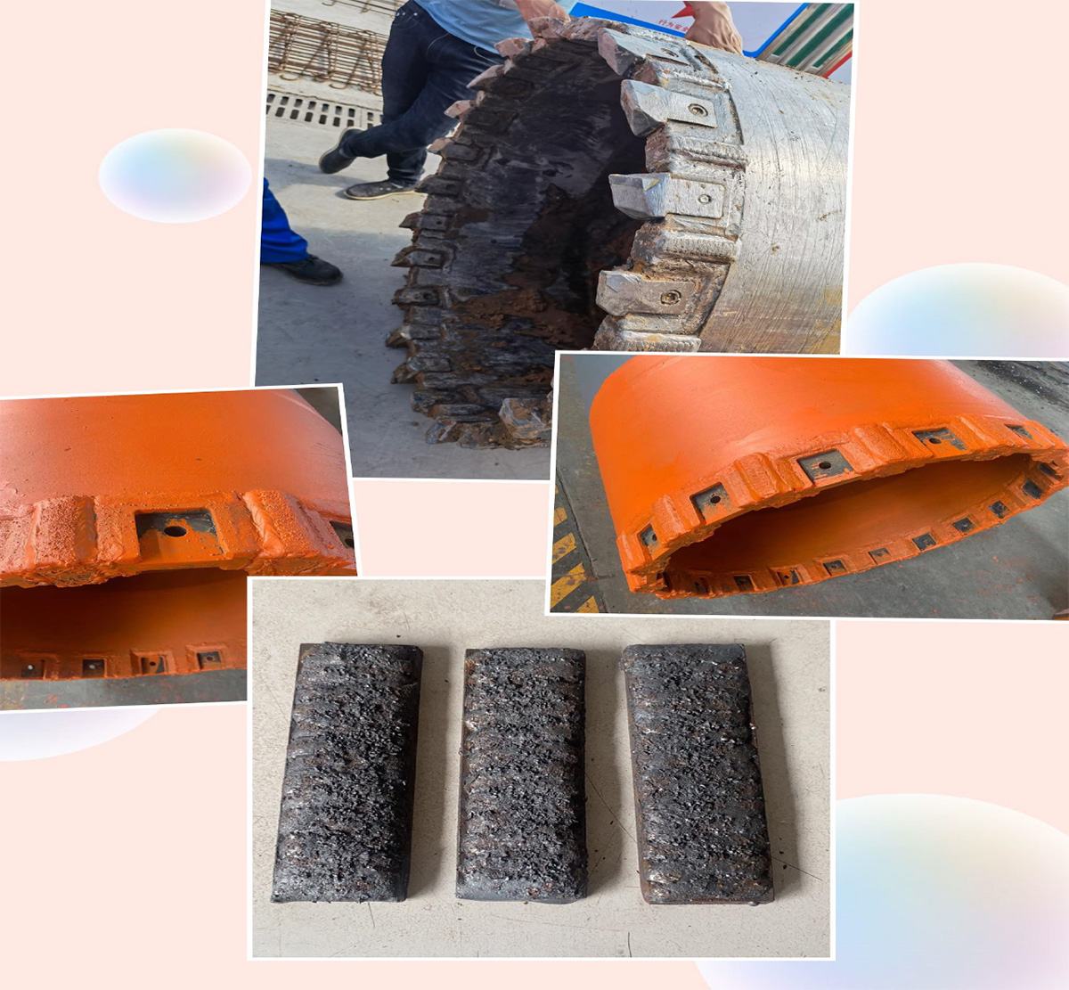
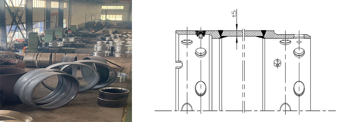
Installation of bottom pipe cutting bucket and cutting tool holder
2. Installation of cutting tool holder
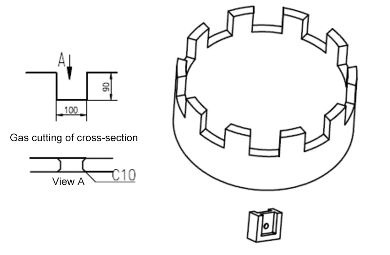
1) Cutting and processing of cutting groove: The quality of cutting and processing of the groove directly affects the welding of the groove. Therefore, it is necessary to control the quality of cutting and processing of the groove according to the following diagram.
2) Welding of cutting tool holder: After cutting and processing the groove of the tool holder, the welding of the tool holder should be carried out firmly without virtual welding. The welding surface of the tool holder weld should be covered with wear-resistant welding.
3) Replacement of cutting tool holder: If the tool head is used continuously beyond the wear limit, it may cause wear of the tool holder. After the wear of the blade holder, it is easy for the blade head to not be firmly fixed, causing shaking and affecting the service life and construction efficiency of the blade. At this time, a new blade holder must be replaced.
Installation of bottom casing and cutting tool holder
3. Wear resistant welding of bottom pipe
When cutting sandy clay, quicksand, bedrock, block stones, isolated stones, etc., the lower end of the tool holder and bottom casing are prone to wear. Therefore, it is necessary to use wear-resistant welding rods to perform wear-resistant welding around the tool holder or weld some wear-resistant blocks with high wear resistance on the outer wall. The function of wear-resistant blocks is not only to reduce the wear of the casing, but also to remove cutting residues, smooth the hole wall, and reduce surface friction resistance.
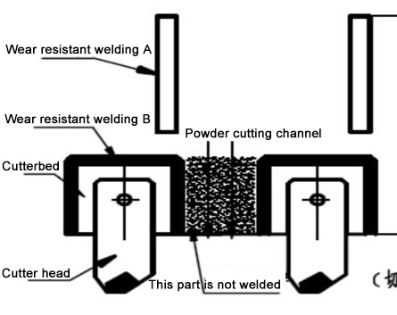
Schematic diagram of wear-resistant overlay welding
1) Selection of welding rod for welding:
During the rotation and compression process of the casing, it is subject to wear and impact from sandy clay, mountain sand, bedrock, block stones, and isolated stones. Therefore, wear-resistant welding rods suitable for the above working conditions should be selected for welding, and YD40 Kengbo customized wear-resistant welding wire should be used. Wear resistant welding wires according to national standards YD322 and YD337 can improve the service life of the bottom sleeve joint.
YD322 wear-resistant welding wire, using DC reverse connection, welding hardness HRC:≥ 50. Used for welding easily worn parts of hydraulic machinery, engineering machinery, mining machinery, etc. that are subject to mud erosion and cavitation damage.
YD337 wear-resistant welding wire, suitable for both AC and DC applications, with a weld hardness of HRC ≥ 60. Used for welding parts with abrasive wear and impact load conditions under normal temperature and non corrosive conditions, such as easily worn parts of mining, engineering, agriculture, brick making, cement, water conservancy and other machinery.
Installation of bottom casing and knife holder
2) Location of wear-resistant overlay welding
The wear-resistant block and wear-resistant welding position A play an important role in smoothing the unevenness of the hole wall, ensuring the gap between the casing and the hole wall, and preventing sand from accumulating on the hole wall. The height of the welding layer should not exceed the protrusion of the cutting tool, preferably 6-8mm, and the length should be controlled at 500mm or more. The purpose of wear-resistant welding at point B is to prevent wear of the cutting tool holder.
3) Chamfering of bottom pipe
When cutting bottom pipes, especially when cutting bedrock, if the slag discharge is not smooth, the slag material cut off is easily accumulated in the cutting groove, causing a sharp increase in torque, greatly affecting cutting efficiency and reducing construction speed. A chamfer can be set at the lower end of the bottom casing to allow cutting slag to be discharged in a timely manner, improve cutting efficiency, and thus increase construction speed. In order to allow the cutting slag to flow better to the inside of the casing, a chamfer angle of 15-20 degrees is selected. To prevent wear on the chamfer, it must be subjected to wear-resistant welding to improve its wear resistance.
Full casing
The role of cutting tools is crucial to ensure the safety of the full rotation and full casing construction method. At the same time, in order to fully utilize the "large cutting torque and high vertical accuracy" of the full rotation full casing construction method, the role of the full casing cannot be ignored.
Construction case of 4-meter diameter full casing
1. Construction of full casing
1) Double layered full casing
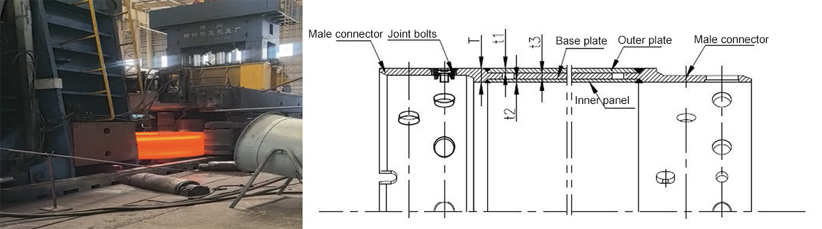
The double layered casing male and female joints are made of 25CrMo forging, and the middle of the casing body is a double-layer structure composed of an outer plate and an inner plate. Insert another layer of padding between the outer and inner panels. The thickness of the joint part (T) is almost the same as the thickness of the outer plate+pad+inner plate (t1+t2+t3=t4). The characteristics of double-layer casing are good rigidity, low deformation and good recovery, strong and durable, but the disadvantages are heavy weight and high cost.
Full sleeve joint forging process
2) Single layer full casing
The single-layer casing male and female joints are made of 25CrMo forging. The casing body is rolled from a whole plate, and there is a step between the pipe body and the male and female joints. The male and female joints are connected by a sliding slope. The characteristic of single-layer casing is that it is lighter in weight and cheaper in price.
Full casing joint processing
3) Types and plate thickness of full casing
At present, there are many manufacturers of full rotation full casing drilling rigs on the market, and the sizes of casing joints, wall thickness, and other dimensions are not uniform. The commonly used ones are shown in the table below.
Statistics of casing information
|
Casing diameter |
1.0m |
1.2m |
1.5m |
1.6m |
1.8/2.0m |
2.4/2.5m |
2.6m |
2.8/3.0/3.2m |
|
Cutter head |
Model |
Quantity |
18 |
21 |
24 |
24 |
27/30 |
36 |
39 |
42/45/45 |
45 angle expansion knife is
used for rocks below 80Mpa |
50 expansion angle knife can cut
steel bars above 80Mpa in rocks |
|
Bolt |
Model |
Quantity |
Double row 12 sets
(5T) |
Double row 12 sets
(5T) |
Double row 16 sets
(5T) |
Double row 16 sets
(5T) |
Double row 20 sets
(5T) |
Double row 24 sets
(7T) |
Double row 30 sets
(7T) |
Double row 28/32/32 groups
(9T) |
|
NCB code of ethics |
M90 |
Male female
combination height |
700mm |
700mm |
700mm |
700mm |
700mm |
760mm |
760mm |
760mm |
|
Thickness |
50 |
50 |
50 |
50 |
50/(60 customized) |
60 |
60 |
70 |
|
Wall thickness |
t25 t30 |
t25 t30 |
t30 |
t30 |
t30 t40 |
t40 |
t40 |
t40 |
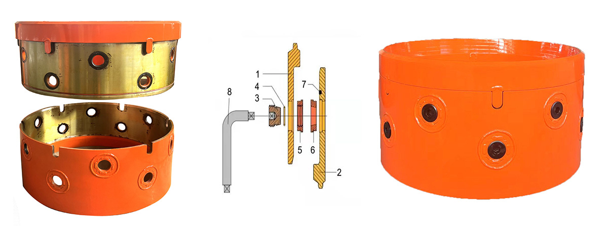
2. Connection of the entire casing
The connection of the male and female joints of the entire casing is fastened using NCB bolts. The complete set of fastening bolts consists of three parts: NCB screws, NCB screw rings, and NCB cone rings, which are fastened using conical surfaces and are not easily loosened. It should be noted that if foreign objects such as soil and sand are mixed into the cone surface, it may cause deformation of the cone surface, welding fracture, insufficient fastening, and inability to loosen during disassembly. It must be cleaned thoroughly before use.
3. The use of full casing
1) The total length of the casing includes various types such as 2, 3, 4, 5, and 6 meters. A 6 meter long casing is commonly used, and the number of casings for each length should be prepared according to the needs during construction. The length of the bottom section casing with a bottom pipe can be appropriately extended.
2) The bottom pipe (the sleeve at the bottom end where the cutting tool is installed) is generally a single-layer pipe made of thick plate. The length is usually around 8m.
3) The casing connected to the bottom pipe is susceptible to impact grabs or impact hammers, causing deformation of the inner plate. The joint between the full casing and the bottom pipe cutting bucket is made of forgings, which greatly increases the turnover rate of the full casing.
4) Even if the shape and diameter of the complete casing, casing joints, and joint bolts are the same, the processing dimensions of the casing and casing joint parts from different manufacturers may also be different. Therefore, when using them, the non universality of products from different manufacturers should be considered.
Full sleeve joint forging process
Summarize
1. During the full casing construction process, the correct installation method, arrangement, and quantity of cutting blades have a significant impact on the efficiency of rotary cutting, affecting the efficiency of construction and determining the lifespan of the cutting blades.
2. Suitable wear-resistant welding and wear-resistant blocks for the bottom pipe are beneficial for slag discharge during construction and effectively reduce frictional resistance during the construction process.
3. Due to the lack of unified construction aids such as full casing and cutting tools for full casing drilling in China, it is recommended to draft a unified industry standard for standardization.


 Contact: Mr.Wang
 Mobile: +86-13585000194 / 15861488616
  Fax: +86-0510-85388408
 Tel: +86-0510-85388408
  E-mail: sales@wxkbjx.com / 502492439@qq.com
 Web: www.520468.cn
  Add: 42 Yuanqiao Road, Yixing Economic Development Zone,Wuxi City, Jiangsu Province